MicroMax's Solutions
MicroMax's Solutions
MicroMax's Solutions
 U100
CAN/CAN-FD to USB Interface
The Kvaser U100 is a robust, single-channel CAN/CAN FD to USB interface with reinforced galvanic isolation that squarely addresses the needs of the evolving automotive development market. Fully compatible with J1939, CANopen, NMEA 2000® and DeviceNet, this is the first in a new range of interfaces that is also suited to rugged applications in marine, industrial, heavy duty vehicle and heavy industries.
Key Features:
Supports CAN FD, up to 8 Mbit/s (with correct physical layer implementation)
Supports both 11-bit (CAN 2.0A) and 29-bit (CAN 2.0B active) identifiers
Powered through the USB connector
Supports bit rates from 10 Kbit/sec up to 1 Mbit/sec
Lightweight, glass fiber reinforced polyamide housing, overmolded with TPE
IP67 rated
DB-9 connector (other connectors available soon)
Intelligent LED UI
Reinforced galvanic isolation, design validated with 5000 VAC RMS applied for 60 seconds
Industrial grade temperature range, −40 °C to +85 °C
20,000 msg/s, each timestamped with a resolution of 100 µs
Support for SocketCAN
Compatible with J1939, CANopen, NMEA 2000® and DeviceNet
Fully compatible with applications written for other Kvaser CAN hardware with Kvaser CANlib
U100
CAN/CAN-FD to USB Interface
The Kvaser U100 is a robust, single-channel CAN/CAN FD to USB interface with reinforced galvanic isolation that squarely addresses the needs of the evolving automotive development market. Fully compatible with J1939, CANopen, NMEA 2000® and DeviceNet, this is the first in a new range of interfaces that is also suited to rugged applications in marine, industrial, heavy duty vehicle and heavy industries.
Key Features:
Supports CAN FD, up to 8 Mbit/s (with correct physical layer implementation)
Supports both 11-bit (CAN 2.0A) and 29-bit (CAN 2.0B active) identifiers
Powered through the USB connector
Supports bit rates from 10 Kbit/sec up to 1 Mbit/sec
Lightweight, glass fiber reinforced polyamide housing, overmolded with TPE
IP67 rated
DB-9 connector (other connectors available soon)
Intelligent LED UI
Reinforced galvanic isolation, design validated with 5000 VAC RMS applied for 60 seconds
Industrial grade temperature range, −40 °C to +85 °C
20,000 msg/s, each timestamped with a resolution of 100 µs
Support for SocketCAN
Compatible with J1939, CANopen, NMEA 2000® and DeviceNet
Fully compatible with applications written for other Kvaser CAN hardware with Kvaser CANlib
 CANFD-LIN-GW
CAN FD LIN Gateway
The CAN-FD LIN Gateway is a user-programmable converter/router/data-logger that features two CAN FD channels, a LIN channel, and a RS-232 port. The converter offers a microSD card slot and multiple digital/analogue inputs and outputs, and its firmware can be developed in C or C++. The device is suitable for a broad range of applications such as protocol conversion, network bridging, data logging, rest-bus simulation, and external peripheral control and monitoring.
Features:
Two high-speed CAN channels with CAN FD support
LIN channel
RS-232 port
MicroSD card slot
4 digital outputs
2 analogue/digital inputs
4 status LEDs
32-bit Arm Cortex-M4 MCU
Freely programmable in C/C++ language
Free-of-charge IDE and C/C++ compiler
Programming examples available
Firmware update over USB, CAN, RS-232 or ICSP
On-board 16 Kbit EEPROM
Externally or USB-powered
Table-top use or DIN-rail mount
Firmware can be developed in C/C++ and can be transferred into the device over USB, CAN, RS-232, or a standard ICSP SWD interface, which also offers code debugging. The device is based on a STM32G4 Arm Cortex-M4 MCU and comes with a free-of-charge IDE, GNU C/C++ compiler, and programming examples.
The on-board EEPROM memory can store user’s application parameters, and the microSD card slot enables the user to load or save large data sets for simulations and data-logging purposes.
The four digital outputs (PWM capable) and the two analogue/digital inputs allow for both input and output triggering. The inputs can read 0-5 V analogue signals, and the outputs offer various output stages (push-pull, HSD, LSD) with currents up to 1.5 A enabling to easily control relays, valves, and other peripherals.
Use Cases:
CAN FD to CAN bridge
LIN to CAN/CAN FD gateway
CAN/LIN bus to RS-232
Data logging
Communication simulation
ECU emulation
Remote monitoring of inputs
Remote control of outputs
CANFD-LIN-GW
CAN FD LIN Gateway
The CAN-FD LIN Gateway is a user-programmable converter/router/data-logger that features two CAN FD channels, a LIN channel, and a RS-232 port. The converter offers a microSD card slot and multiple digital/analogue inputs and outputs, and its firmware can be developed in C or C++. The device is suitable for a broad range of applications such as protocol conversion, network bridging, data logging, rest-bus simulation, and external peripheral control and monitoring.
Features:
Two high-speed CAN channels with CAN FD support
LIN channel
RS-232 port
MicroSD card slot
4 digital outputs
2 analogue/digital inputs
4 status LEDs
32-bit Arm Cortex-M4 MCU
Freely programmable in C/C++ language
Free-of-charge IDE and C/C++ compiler
Programming examples available
Firmware update over USB, CAN, RS-232 or ICSP
On-board 16 Kbit EEPROM
Externally or USB-powered
Table-top use or DIN-rail mount
Firmware can be developed in C/C++ and can be transferred into the device over USB, CAN, RS-232, or a standard ICSP SWD interface, which also offers code debugging. The device is based on a STM32G4 Arm Cortex-M4 MCU and comes with a free-of-charge IDE, GNU C/C++ compiler, and programming examples.
The on-board EEPROM memory can store user’s application parameters, and the microSD card slot enables the user to load or save large data sets for simulations and data-logging purposes.
The four digital outputs (PWM capable) and the two analogue/digital inputs allow for both input and output triggering. The inputs can read 0-5 V analogue signals, and the outputs offer various output stages (push-pull, HSD, LSD) with currents up to 1.5 A enabling to easily control relays, valves, and other peripherals.
Use Cases:
CAN FD to CAN bridge
LIN to CAN/CAN FD gateway
CAN/LIN bus to RS-232
Data logging
Communication simulation
ECU emulation
Remote monitoring of inputs
Remote control of outputs
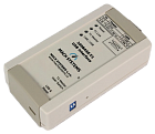
 100BASET1-MC-ETH
100BASE-T1 to 100BASE-TX (Fast Ethernet) Media Converter
A bi-directional physical layer converter between 100BASE-T1 (OPEN Alliance BroadR-Reach — OABR) and 100BASE-TX (Fast Ethernet), enabling the user to easily connect Automotive Ethernet cameras or ECUs with OABR media link to a standard computer network.
The interface establishes a point-to-point link between an unshielded twisted-pair Automotive Ethernet (IEEE 100BASE-T1) port and a Fast Ethernet port. The converter features one DSUB9 (BroadR-Reach, CAN bus), one Fast Ethernet port with RJ-45 connector, and a Micro-USB connector. The BroadR-Reach channel is configurable as either Master or Slave by a switch button or programmatically, and the device can be powered either via DSUB connector or via USB.
Features
100BASE-T1 (IEEE 802.3bw) to 100BASE-TX media conversion
Master/Slave configuration for BroadR-Reach
DSUB9 connector for T1, RJ-45 connector for Ethernet
USB-powered or externally powered
6 status LEDs
2 DIP switches
Automatic polarity detection for OABR Slave
Media test for T1 cable — can detect a shortage, cut-off and impedance mismatch
Table top or DIN-rail mount
The converter offers a possibility to access SMI registers of both transreceivers (PHYs) via a CAN bus or a USB’s virtual serial port. This enables the user to evaluate signal strength, detect polarity of the T1 port, carry out a BroadR-Reach media test to diagnose cable errors, fine-tune the PHYs parameters, and generally to read and write the registers.
Free PC application for Status Information
A free-of-charge PC utility for reading status information out of the 100BASE-T1 Media Converter. Once you plug the Media Converter into computer’s USB port, the PC utility will show you converter’s port status, signal quality and T1 cable test result. This is useful for diagnostic and test purposes.
100BASET1-MC-ETH
100BASE-T1 to 100BASE-TX (Fast Ethernet) Media Converter
A bi-directional physical layer converter between 100BASE-T1 (OPEN Alliance BroadR-Reach — OABR) and 100BASE-TX (Fast Ethernet), enabling the user to easily connect Automotive Ethernet cameras or ECUs with OABR media link to a standard computer network.
The interface establishes a point-to-point link between an unshielded twisted-pair Automotive Ethernet (IEEE 100BASE-T1) port and a Fast Ethernet port. The converter features one DSUB9 (BroadR-Reach, CAN bus), one Fast Ethernet port with RJ-45 connector, and a Micro-USB connector. The BroadR-Reach channel is configurable as either Master or Slave by a switch button or programmatically, and the device can be powered either via DSUB connector or via USB.
Features
100BASE-T1 (IEEE 802.3bw) to 100BASE-TX media conversion
Master/Slave configuration for BroadR-Reach
DSUB9 connector for T1, RJ-45 connector for Ethernet
USB-powered or externally powered
6 status LEDs
2 DIP switches
Automatic polarity detection for OABR Slave
Media test for T1 cable — can detect a shortage, cut-off and impedance mismatch
Table top or DIN-rail mount
The converter offers a possibility to access SMI registers of both transreceivers (PHYs) via a CAN bus or a USB’s virtual serial port. This enables the user to evaluate signal strength, detect polarity of the T1 port, carry out a BroadR-Reach media test to diagnose cable errors, fine-tune the PHYs parameters, and generally to read and write the registers.
Free PC application for Status Information
A free-of-charge PC utility for reading status information out of the 100BASE-T1 Media Converter. Once you plug the Media Converter into computer’s USB port, the PC utility will show you converter’s port status, signal quality and T1 cable test result. This is useful for diagnostic and test purposes.
 100BASET1-USB-IF
100BASE-T1 USB Interface
The 100BASE-T1 USB Interface (Media Converter) connects a 100BASE-T1 network to any computer with an USB port. The converter acts as an Ethernet network interface card when plugged into an USB port. The interface easily connects Automotive Ethernet devices with OPEN Alliance BroadR-Reach (OABR) port, such as cameras or ECUs, directly to any PC without a need of an on-board network card.
The interface establishes a point-to-point link between an unshielded twisted-pair IEEE 100BASE-T1 (IEEE 802.3bw) port and USB-LAN port, and works as a Network Interface Card allowing the user to configure the network adapter’s parameters, such as IP address and mask. The converter features a DSUB9 (BroadR-Reach, CAN bus) and Micro-USB connector. The OABR channel’s Master/Slave configuration is selected by a switch button or programmatically.
Features
100BASE-T1 (IEEE 802.3bw) to USB-LAN Interface
Acts as USB 2.0 Network Adapter Card
Master / Slave configuration by on-board dip switches or programmatically
USB powered
4 Status LEDs
DSUB9 connector for T1 and CAN bus, Micro-USB for USB 2.0
Automatic polarity detection for OABR Slave
Media test for T1 cable — can detect a shortage, cut-off and impedance mismatch
Table top or DIN-rail mount
Configuration and diagostic over USB COM port (CDC) and CAN bus
100BASE-T1 USB Interface offers a possibility to access SMI registers of the 100BASE-T1 transreceiver (PHY) via a CAN bus or a USB’s virtual serial port. This enables the user to evaluate signal strength, detect polarity of the T1 port, carry out a BroadR-Reach media test to diagnose cable errors, fine-tune the PHYs parameters, and generally to read and write the registers.
Free PC application for Status Information
A free-of-charge PC utility for reading status information out of the 100BASE-T1 USB Interface. Once you plug the adapter into computer’s USB port, the PC utility will show you interface’s port status, signal quality and T1 cable test result. This is useful for diagnostic and test purposes. The utility can also override Master/Slave configuration for T1 port.
100BASET1-USB-IF
100BASE-T1 USB Interface
The 100BASE-T1 USB Interface (Media Converter) connects a 100BASE-T1 network to any computer with an USB port. The converter acts as an Ethernet network interface card when plugged into an USB port. The interface easily connects Automotive Ethernet devices with OPEN Alliance BroadR-Reach (OABR) port, such as cameras or ECUs, directly to any PC without a need of an on-board network card.
The interface establishes a point-to-point link between an unshielded twisted-pair IEEE 100BASE-T1 (IEEE 802.3bw) port and USB-LAN port, and works as a Network Interface Card allowing the user to configure the network adapter’s parameters, such as IP address and mask. The converter features a DSUB9 (BroadR-Reach, CAN bus) and Micro-USB connector. The OABR channel’s Master/Slave configuration is selected by a switch button or programmatically.
Features
100BASE-T1 (IEEE 802.3bw) to USB-LAN Interface
Acts as USB 2.0 Network Adapter Card
Master / Slave configuration by on-board dip switches or programmatically
USB powered
4 Status LEDs
DSUB9 connector for T1 and CAN bus, Micro-USB for USB 2.0
Automatic polarity detection for OABR Slave
Media test for T1 cable — can detect a shortage, cut-off and impedance mismatch
Table top or DIN-rail mount
Configuration and diagostic over USB COM port (CDC) and CAN bus
100BASE-T1 USB Interface offers a possibility to access SMI registers of the 100BASE-T1 transreceiver (PHY) via a CAN bus or a USB’s virtual serial port. This enables the user to evaluate signal strength, detect polarity of the T1 port, carry out a BroadR-Reach media test to diagnose cable errors, fine-tune the PHYs parameters, and generally to read and write the registers.
Free PC application for Status Information
A free-of-charge PC utility for reading status information out of the 100BASE-T1 USB Interface. Once you plug the adapter into computer’s USB port, the PC utility will show you interface’s port status, signal quality and T1 cable test result. This is useful for diagnostic and test purposes. The utility can also override Master/Slave configuration for T1 port.
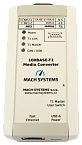
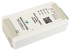
 LIN-CAN/RS-232
LIN - CAN/RS-232 Gateway
The LIN to CAN and LIN to RS-232 Gateways can be used to interface a LIN bus to CAN or RS-232 respectively. The converters can act as both LIN Master and Slave. A typical use-case is to control or monitor a LIN bus from a PLC with RS-232 port over the gateway device, or simply to bridge a LIN network to a CAN bus.
Both LIN-CAN and LIN-RS232 are available in the following firmware options:
Universal gateway
The communication protocol allows to fully control the LIN bus. The user can transmit and receive LIN frames (more details below)
Configurable CAN-LIN Gateway (LIN-CAN device only)
The user configures the mapping between CAN and LIN (CAN id to LIN id), CAN and LIN channel parameters, LIN scheduler, and stores the configuration into an internal non-volatile memory.
The gateway automatically forwards data from given received CAN Id to LIN bus and vice versa. This options comes with a free-of-charge PC application for configuration.
Without firmware
The firmware is developed according to customer needs or the customer can develop the firmware it by himself.
Universal Gateway Firmware
The universal gateway firmware for both LIN-CAN and LIN-RS232 devices provides the user a full control of the LIN bus communication. With the help of the communication protocol for RS-232 and CAN bus, the user can configure the gateway and communicate with the LIN bus. The device can act as LIN Master, LIN Slave, or LIN sniffer. The user can transmit and receive LIN frames, or simply monitor LIN bus communication.
The universal firmware enables to act as:
LIN Master
LIN Slave
LIN Monitor (communication sniffer)
The communication protocol allows to:
Configure the LIN channel (Master/Slave, Baud Rate, Checksum type)
Transmit: Master Request, Master Responses
Receive: Slave Responses
Simulate Slave
Sniffer: receive all LIN communication
Gateway without Firmware
The device‘s firmware is customizable on request and can be flashed into the device via CAN bus or RS-232 respectively. Source code examples (CAN, LIN, RS-232, Timer) can be provided on request so that the user can develop his own application based on the device. We can also provide a full LIN stack (C code).
LIN-CAN/RS-232
LIN - CAN/RS-232 Gateway
The LIN to CAN and LIN to RS-232 Gateways can be used to interface a LIN bus to CAN or RS-232 respectively. The converters can act as both LIN Master and Slave. A typical use-case is to control or monitor a LIN bus from a PLC with RS-232 port over the gateway device, or simply to bridge a LIN network to a CAN bus.
Both LIN-CAN and LIN-RS232 are available in the following firmware options:
Universal gateway
The communication protocol allows to fully control the LIN bus. The user can transmit and receive LIN frames (more details below)
Configurable CAN-LIN Gateway (LIN-CAN device only)
The user configures the mapping between CAN and LIN (CAN id to LIN id), CAN and LIN channel parameters, LIN scheduler, and stores the configuration into an internal non-volatile memory.
The gateway automatically forwards data from given received CAN Id to LIN bus and vice versa. This options comes with a free-of-charge PC application for configuration.
Without firmware
The firmware is developed according to customer needs or the customer can develop the firmware it by himself.
Universal Gateway Firmware
The universal gateway firmware for both LIN-CAN and LIN-RS232 devices provides the user a full control of the LIN bus communication. With the help of the communication protocol for RS-232 and CAN bus, the user can configure the gateway and communicate with the LIN bus. The device can act as LIN Master, LIN Slave, or LIN sniffer. The user can transmit and receive LIN frames, or simply monitor LIN bus communication.
The universal firmware enables to act as:
LIN Master
LIN Slave
LIN Monitor (communication sniffer)
The communication protocol allows to:
Configure the LIN channel (Master/Slave, Baud Rate, Checksum type)
Transmit: Master Request, Master Responses
Receive: Slave Responses
Simulate Slave
Sniffer: receive all LIN communication
Gateway without Firmware
The device‘s firmware is customizable on request and can be flashed into the device via CAN bus or RS-232 respectively. Source code examples (CAN, LIN, RS-232, Timer) can be provided on request so that the user can develop his own application based on the device. We can also provide a full LIN stack (C code).
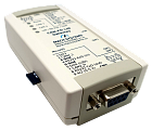
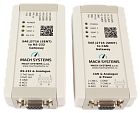 SENT-CAN/RS-232
SAE J2716 (SENT) to CAN/RS-232 Gateway
The SAE J2716 (SENT) to RS-232/CAN bus gateway features two bi-directional SENT (Single Edge Nibble Transmission) channels, two analogue output channels, and either RS-232 or CAN bus interface. The flexibility of the device allows the user to use it as a PC interface / SENT data logger, a gateway for PLC or a test system, and generally for SENT communication monitoring and simulation. The analogue outputs offer the possibility to directly convert SENT data frame signals into an analogue voltage.
Features
SENT-to-CAN or SENT-to-RS-232 Gateway
SENT logger/tester/simulator
2 SAE J2716 (SENT) channels
Each channel configurable as RX or TX, channels are independent
Supports Fast and Slow Messages according to SAE J2716:2016 (Fast, Short Serial, and Enhanced Serial)
Supports SENT/SPC
Configurable SENT channel parameters — Tick Time, Nibble Count
2 analogue output channels (12-bit DAC, 0-4,095 V)
On-board remanent memory
Intelligent message filtration
1x DSUB9F (RS-232/CAN), 1×8-pin terminal block
Input power 9-30 V DC
4x LED (3x Status, 1x Power)
1x Reset switch
5V DC output with over-current protection
Dimensions 108×54×30 mm
Table or DIN-rail mount
Hardware and firmware customization on request
Fast, Short Serial, and Enhanced Serial message formats are supported. The user can configure channel parameters (direction, tick time, nibble count, filtration) and store the configuration into the device’s non-volatile memory. Each SENT channel can be configured independently to suit all possible use cases: 2 RX channels / 1 RX and 1 TX channel / 2 TX channels.
The converter offers two analogue output channels (12-bit DAC) that can be used to directly convert inbound SENT data frames into an analogue voltage. An analogue output channel can be mapped on any SENT channel. and the conversion parameters are fully configurable: StartBit, BitLength and a linear transfer function: Multiplier, Offset, Min/Max.
An intelligent filtration of incoming SENT frames has been introduced so that RS-232 or CAN communication does not get overloaded. The CAN variant offers configurable CAN Identifiers for both TX and RX which allows multiple devices to be used simultaneously on the same CAN bus. The device’s firmware is upgradable from PC.
A PC application «SENT Gateway Analyser» for configuring the device and for monitoring, logging and simulation of SENT communication is available for free. The device provides a communication protocol over RS-232/CAN so that the user can easily integrate the device into an existing system, such as test benches, HiL rigs and End-of-Line testers. The protocol provides function to configure the device’s SENT and analogue channels and to transmit and receive SENT Fast and Slow messages.
Software and System Integration
Communication protocol for integration into existing systems
Free-of-charge «SENT Gateway Analyser» PC application for configuration, reception, transmission and logging
note: The SENT Gateway Analyser application will work with any RS-232 port (COM port). For usage with SENT-CAN variant, the SENT Gateway Analyser uses Kvaser CAN driver for communicating over a CAN bus. Hence, a CAN interface by Kvaser is needed for communication with the SENT-CAN variant. The user can still control the device by raw CAN messages.
Analogue output channels to connect SAE J2716 bus to systems without SENT support
Device’s firmware upgradable from PC
SENT-CAN/RS-232
SAE J2716 (SENT) to CAN/RS-232 Gateway
The SAE J2716 (SENT) to RS-232/CAN bus gateway features two bi-directional SENT (Single Edge Nibble Transmission) channels, two analogue output channels, and either RS-232 or CAN bus interface. The flexibility of the device allows the user to use it as a PC interface / SENT data logger, a gateway for PLC or a test system, and generally for SENT communication monitoring and simulation. The analogue outputs offer the possibility to directly convert SENT data frame signals into an analogue voltage.
Features
SENT-to-CAN or SENT-to-RS-232 Gateway
SENT logger/tester/simulator
2 SAE J2716 (SENT) channels
Each channel configurable as RX or TX, channels are independent
Supports Fast and Slow Messages according to SAE J2716:2016 (Fast, Short Serial, and Enhanced Serial)
Supports SENT/SPC
Configurable SENT channel parameters — Tick Time, Nibble Count
2 analogue output channels (12-bit DAC, 0-4,095 V)
On-board remanent memory
Intelligent message filtration
1x DSUB9F (RS-232/CAN), 1×8-pin terminal block
Input power 9-30 V DC
4x LED (3x Status, 1x Power)
1x Reset switch
5V DC output with over-current protection
Dimensions 108×54×30 mm
Table or DIN-rail mount
Hardware and firmware customization on request
Fast, Short Serial, and Enhanced Serial message formats are supported. The user can configure channel parameters (direction, tick time, nibble count, filtration) and store the configuration into the device’s non-volatile memory. Each SENT channel can be configured independently to suit all possible use cases: 2 RX channels / 1 RX and 1 TX channel / 2 TX channels.
The converter offers two analogue output channels (12-bit DAC) that can be used to directly convert inbound SENT data frames into an analogue voltage. An analogue output channel can be mapped on any SENT channel. and the conversion parameters are fully configurable: StartBit, BitLength and a linear transfer function: Multiplier, Offset, Min/Max.
An intelligent filtration of incoming SENT frames has been introduced so that RS-232 or CAN communication does not get overloaded. The CAN variant offers configurable CAN Identifiers for both TX and RX which allows multiple devices to be used simultaneously on the same CAN bus. The device’s firmware is upgradable from PC.
A PC application «SENT Gateway Analyser» for configuring the device and for monitoring, logging and simulation of SENT communication is available for free. The device provides a communication protocol over RS-232/CAN so that the user can easily integrate the device into an existing system, such as test benches, HiL rigs and End-of-Line testers. The protocol provides function to configure the device’s SENT and analogue channels and to transmit and receive SENT Fast and Slow messages.
Software and System Integration
Communication protocol for integration into existing systems
Free-of-charge «SENT Gateway Analyser» PC application for configuration, reception, transmission and logging
note: The SENT Gateway Analyser application will work with any RS-232 port (COM port). For usage with SENT-CAN variant, the SENT Gateway Analyser uses Kvaser CAN driver for communicating over a CAN bus. Hence, a CAN interface by Kvaser is needed for communication with the SENT-CAN variant. The user can still control the device by raw CAN messages.
Analogue output channels to connect SAE J2716 bus to systems without SENT support
Device’s firmware upgradable from PC
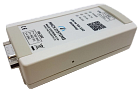
 SENT-USB
SAE J2716 (SENT) – USB Interface
The SENT-USB is a two-channel SAE J2716 (Single Edge Nibble Transmission — SENT) to USB interface that easily connects a SENT bus to any computer with an USB port. The converter is powered from USB and features two bi-directional SENT channels and an USB virtual COM port. The device comes with a free-of-charge PC application for SENT communication analysis and simulation. An open communication protocol over the virtual serial port enables the user to integrate the interface into an existing system.
Two SAE J2716 (SENT) channels
Each channel configurable as TX/RX
USB Interface (Virtual COM port)
USB-powered
Configurable SENT channel parameters
Supports Fast, Short Serial, and Enhanced Serial messages
Supports SPC mode
On-board non-volatile memory
Intelligent message filtration
Free PC application for configuration, reception, transmission and logging
Communication protocol for integration into existing systems
Device’s firmware upgradable over USB
Table or DIN-rail mount
Hardware and firmware customization on request
Each SENT channel can be configured independently to suit all use cases: 2 RX channels / 1 RX and 1 TX channel / 2 TX channels. Channel parameters (direction, tick time, nibble count, filtration) are configurable and the configuration can be stored in the device’s non-volatile memory. Fast, Short Serial, and Enhanced Serial message formats are supported. An intelligent filtration of incoming SENT frames has been introduced so that serial communication does not get overloaded.
A PC application for configuring the device and for monitoring, logging and simulation of SENT communication is available for free. The device offers a communication protocol over its USB virtual COM port (VCP) so that the user can easily integrate the device into an existing system, such as test benches and HiL rigs. The protocol enables the user to configure the device’s parameters as well as transmit and receive SENT Fast and Slow messages.
SENT-USB
SAE J2716 (SENT) – USB Interface
The SENT-USB is a two-channel SAE J2716 (Single Edge Nibble Transmission — SENT) to USB interface that easily connects a SENT bus to any computer with an USB port. The converter is powered from USB and features two bi-directional SENT channels and an USB virtual COM port. The device comes with a free-of-charge PC application for SENT communication analysis and simulation. An open communication protocol over the virtual serial port enables the user to integrate the interface into an existing system.
Two SAE J2716 (SENT) channels
Each channel configurable as TX/RX
USB Interface (Virtual COM port)
USB-powered
Configurable SENT channel parameters
Supports Fast, Short Serial, and Enhanced Serial messages
Supports SPC mode
On-board non-volatile memory
Intelligent message filtration
Free PC application for configuration, reception, transmission and logging
Communication protocol for integration into existing systems
Device’s firmware upgradable over USB
Table or DIN-rail mount
Hardware and firmware customization on request
Each SENT channel can be configured independently to suit all use cases: 2 RX channels / 1 RX and 1 TX channel / 2 TX channels. Channel parameters (direction, tick time, nibble count, filtration) are configurable and the configuration can be stored in the device’s non-volatile memory. Fast, Short Serial, and Enhanced Serial message formats are supported. An intelligent filtration of incoming SENT frames has been introduced so that serial communication does not get overloaded.
A PC application for configuring the device and for monitoring, logging and simulation of SENT communication is available for free. The device offers a communication protocol over its USB virtual COM port (VCP) so that the user can easily integrate the device into an existing system, such as test benches and HiL rigs. The protocol enables the user to configure the device’s parameters as well as transmit and receive SENT Fast and Slow messages.
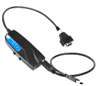 Memorator Light HS v2
CAN-USB interface
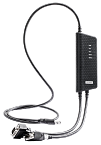
Designed for troubleshooting any CAN-based (controller area network) system, the Kvaser Memorator Light HS v2 is an easy-to-use tool for logging serial data, with no software setup required. With an autobaud function that determines CAN bus bit rate, the Kvaser Memorator Light can be attached to any high-speed CAN bus without configuration. All CAN bus traffic is logged in a circular buffer, overwriting the oldest data when the buffer becomes full. A separate circular buffer keeps track of error frame conditions and the message traffic that occurs near the conditions.
Major Features
Single high-speed CAN channel (compliant with ISO 11898-2).
Supports both 11-bit (CAN 2.0A) and 29-bit (CAN 2.0B active) identifiers.
Supports bit rates from 50 Kbit/sec up to 1 Mbit/sec.
Autobaud function determines CAN bus bit rate.
Always in silent mode — log bus traffic without interfering.
Fixed 1GB internal storage.
Two FIFO buffers; one logs all messages on the bus, the other buffer logs approximately 1000 messages before and after an error frame.
Built-in real time clock (calendar) with battery backup.
LEDs alert the user to device status.
Note: The Kvaser Memorator Light HS v2 does not operate as an interface (i.e. provide real-time access to the CANbus). For a device that functions as both a standalone datalogger and CANbus interface, the Kvaser Memorator 2xHS v2, Kvaser Memorator Pro 2xHS v2, and Kvaser Memorator Pro 5xHS are recommended.
Software
Documentation, Kvaser CANlib SDK and drivers can be downloaded for free at www.kvaser.com/downloads.
Kvaser CANlib SDK is a free resource that includes everything you need to develop software for the Kvaser CAN interfaces. Includes full documentation and many program samples, written in C, C++, C#, Delphi, Visual Basic, Python and t programming language.
Kvaser CAN hardware is built around the same common software API. Applications developed using one device type will run without modification on other device types.
The Kvaser Memorator Config Tool provides easy access to the recorded data when connected to the device via a USB port. The tool supports multiple formats used by popular analysis software. In addition, the extraction software allows the user to clear and reinitialize the device’s memory.
Memorator Light HS v2
CAN-USB interface
Designed for troubleshooting any CAN-based (controller area network) system, the Kvaser Memorator Light HS v2 is an easy-to-use tool for logging serial data, with no software setup required. With an autobaud function that determines CAN bus bit rate, the Kvaser Memorator Light can be attached to any high-speed CAN bus without configuration. All CAN bus traffic is logged in a circular buffer, overwriting the oldest data when the buffer becomes full. A separate circular buffer keeps track of error frame conditions and the message traffic that occurs near the conditions.
Major Features
Single high-speed CAN channel (compliant with ISO 11898-2).
Supports both 11-bit (CAN 2.0A) and 29-bit (CAN 2.0B active) identifiers.
Supports bit rates from 50 Kbit/sec up to 1 Mbit/sec.
Autobaud function determines CAN bus bit rate.
Always in silent mode — log bus traffic without interfering.
Fixed 1GB internal storage.
Two FIFO buffers; one logs all messages on the bus, the other buffer logs approximately 1000 messages before and after an error frame.
Built-in real time clock (calendar) with battery backup.
LEDs alert the user to device status.
Note: The Kvaser Memorator Light HS v2 does not operate as an interface (i.e. provide real-time access to the CANbus). For a device that functions as both a standalone datalogger and CANbus interface, the Kvaser Memorator 2xHS v2, Kvaser Memorator Pro 2xHS v2, and Kvaser Memorator Pro 5xHS are recommended.
Software
Documentation, Kvaser CANlib SDK and drivers can be downloaded for free at www.kvaser.com/downloads.
Kvaser CANlib SDK is a free resource that includes everything you need to develop software for the Kvaser CAN interfaces. Includes full documentation and many program samples, written in C, C++, C#, Delphi, Visual Basic, Python and t programming language.
Kvaser CAN hardware is built around the same common software API. Applications developed using one device type will run without modification on other device types.
The Kvaser Memorator Config Tool provides easy access to the recorded data when connected to the device via a USB port. The tool supports multiple formats used by popular analysis software. In addition, the extraction software allows the user to clear and reinitialize the device’s memory.
 Hybrid Pro 2xCAN/LIN
Dual channel USB-CAN/LIN interface with CAN FD support
Kvaser Hybrid Pro 2xCAN/LIN is a flexible, dual channel interface that allows each channel to be assigned independently as CAN, CAN FD or LIN. This makes the Kvaser Hybrid Pro 2xCAN/LIN a must-have ’universal interface’ for every engineer involved in automotive communications!
The Kvaser Hybrid Pro 2xCAN/LIN offers advanced features such as support for CAN FD, Silent Mode, Single Shot, Error Frame Generation and Kvaser MagiSync automatic clock synchronization. As a Pro-level device, this interface can host user-developed programs, created using resources provided within Kvaser’s free CANlib SDK. These can be designed to accomplish a range of advanced tasks, such as CAN node simulation and CAN flashing, or create a LIN to CAN gateway. Guidance and code examples are provided.
Main Features:
Hybrid USB CAN/LIN two channel interface with two separate 9-pin D-SUBs
t programs allow users to customise the Hybrid Pro 2xCAN/LIN’s behaviour
Supports High Speed CAN (ISO 11898-2) up to 1Mbit/s and LIN 2.2A (ISO 17987 Part 1-7) up to 20 kbit/s
Supports CAN FD (ISO 11898-1) up to 5 Mbit/s (with correct physical layer implementation)
Capable of sending up to 20000 messages per second, per CAN channel, time-stamped with a 1 microsecond accuracy
USB powered (bus V+ reference required for LIN)
Kvaser MagiSync — automatic time synchronization between MagiSync-enabled Kvaser interfaces connected to the same PC
Single shot function ensures that failed CAN transmissions will not retry
CAN Error Frame Generation and Error Counters
LED lights indicate device status
Fully compatible with J1939, CANopen, NMEA 2000 and DeviceNet
Supplied with Kvaser CANlib and Kvaser LINlib, free software APIs that are common to all Kvaser hardware and enable the channels to be configured intuitively and fast
Extended operating temperature range from −40 to 85 °C
Support for SocketCAN, see elinux.org for details
Software
Documentation, Kvaser CANlib SDK and drivers can be downloaded for free at www.kvaser.com/downloads
Kvaser CANlib SDK is a free resource that includes everything you need to develop software for the Kvaser CAN and LIN interfaces. Includes full documentation and many program samples, written in C, C++, C#, Delphi, Visual Basic, Python, as well as Kvaser’s t Programming language
All Kvaser CAN interface boards share the common software API, CANlib SDK. Programs written for one interface type will run without modifications on the other interface types
J2534 Application Programming Interface available
RP1210A Application Programming Interface available
HTML-Help and online documentation in Windows and Linux
Hybrid Pro 2xCAN/LIN
Dual channel USB-CAN/LIN interface with CAN FD support
Kvaser Hybrid Pro 2xCAN/LIN is a flexible, dual channel interface that allows each channel to be assigned independently as CAN, CAN FD or LIN. This makes the Kvaser Hybrid Pro 2xCAN/LIN a must-have ’universal interface’ for every engineer involved in automotive communications!
The Kvaser Hybrid Pro 2xCAN/LIN offers advanced features such as support for CAN FD, Silent Mode, Single Shot, Error Frame Generation and Kvaser MagiSync automatic clock synchronization. As a Pro-level device, this interface can host user-developed programs, created using resources provided within Kvaser’s free CANlib SDK. These can be designed to accomplish a range of advanced tasks, such as CAN node simulation and CAN flashing, or create a LIN to CAN gateway. Guidance and code examples are provided.
Main Features:
Hybrid USB CAN/LIN two channel interface with two separate 9-pin D-SUBs
t programs allow users to customise the Hybrid Pro 2xCAN/LIN’s behaviour
Supports High Speed CAN (ISO 11898-2) up to 1Mbit/s and LIN 2.2A (ISO 17987 Part 1-7) up to 20 kbit/s
Supports CAN FD (ISO 11898-1) up to 5 Mbit/s (with correct physical layer implementation)
Capable of sending up to 20000 messages per second, per CAN channel, time-stamped with a 1 microsecond accuracy
USB powered (bus V+ reference required for LIN)
Kvaser MagiSync — automatic time synchronization between MagiSync-enabled Kvaser interfaces connected to the same PC
Single shot function ensures that failed CAN transmissions will not retry
CAN Error Frame Generation and Error Counters
LED lights indicate device status
Fully compatible with J1939, CANopen, NMEA 2000 and DeviceNet
Supplied with Kvaser CANlib and Kvaser LINlib, free software APIs that are common to all Kvaser hardware and enable the channels to be configured intuitively and fast
Extended operating temperature range from −40 to 85 °C
Support for SocketCAN, see elinux.org for details
Software
Documentation, Kvaser CANlib SDK and drivers can be downloaded for free at www.kvaser.com/downloads
Kvaser CANlib SDK is a free resource that includes everything you need to develop software for the Kvaser CAN and LIN interfaces. Includes full documentation and many program samples, written in C, C++, C#, Delphi, Visual Basic, Python, as well as Kvaser’s t Programming language
All Kvaser CAN interface boards share the common software API, CANlib SDK. Programs written for one interface type will run without modifications on the other interface types
J2534 Application Programming Interface available
RP1210A Application Programming Interface available
HTML-Help and online documentation in Windows and Linux
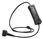
 Leaf Light HS v2 J1939-13 Type II
J1939 compliant CAN-USB interface
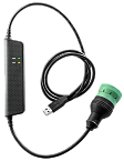
The Leaf Light HS v2 J1939-13 Type II provides a simple way of connecting a PC with the on-board computer of any J1939 compliant vehicle or industrial system. Get diagnostic data by means of its USB 2.0 connector and a 9-pin J1939-13 (Type II) compliant CAN connector, which is colour-coded in green and supports either 250 Kbps or 500 Kbps vehicle networks.
The Leaf Light HS v2 J1939-13 Type II belongs to Kvaser’s Leaf Light product range, which has made its name as the work-horse of the CAN interface world by offering a reliable, low cost means of connecting any CAN network to a PC or mobile computer.
Major Features
Standard type «A» USB connector and a J1939-13 Type II compliant CAN connector.
Capable of sending up to 8000 messages per second, each time-stamped with 100 microsecond accuracy.
Supports both 11-bit (CAN 2.0A) and 29-bit (CAN 2.0B active) identifiers.
High-speed CAN connection (compliant with ISO 11898-2), up to 1 Mbit/s.
Galvanic isolation, enhancing protection from power surges or electrical shocks.
Support for SocketCAN, see elinux.org for details.
Software
Documentation, software and drivers can be downloaded for free at www.kvaser.com/downloads.
Kvaser CANLIB SDK is a free resource that includes everything you need to develop software for the Kvaser CAN interfaces.
Includes full documentation and many program samples, written in C, C++, C#, Delphi, Java, Python and Visual Basic.
All Kvaser CAN interface boards share a common software API. Programs written for one interface type will run without modifications on the other interface types!
J2534 Application Programming Interface available.
RP1210A Application Programming Interface available.On-line documentation in Windows HTML-Help and Adobe Acrobat format.
Leaf Light HS v2 J1939-13 Type II
J1939 compliant CAN-USB interface
The Leaf Light HS v2 J1939-13 Type II provides a simple way of connecting a PC with the on-board computer of any J1939 compliant vehicle or industrial system. Get diagnostic data by means of its USB 2.0 connector and a 9-pin J1939-13 (Type II) compliant CAN connector, which is colour-coded in green and supports either 250 Kbps or 500 Kbps vehicle networks.
The Leaf Light HS v2 J1939-13 Type II belongs to Kvaser’s Leaf Light product range, which has made its name as the work-horse of the CAN interface world by offering a reliable, low cost means of connecting any CAN network to a PC or mobile computer.
Major Features
Standard type «A» USB connector and a J1939-13 Type II compliant CAN connector.
Capable of sending up to 8000 messages per second, each time-stamped with 100 microsecond accuracy.
Supports both 11-bit (CAN 2.0A) and 29-bit (CAN 2.0B active) identifiers.
High-speed CAN connection (compliant with ISO 11898-2), up to 1 Mbit/s.
Galvanic isolation, enhancing protection from power surges or electrical shocks.
Support for SocketCAN, see elinux.org for details.
Software
Documentation, software and drivers can be downloaded for free at www.kvaser.com/downloads.
Kvaser CANLIB SDK is a free resource that includes everything you need to develop software for the Kvaser CAN interfaces.
Includes full documentation and many program samples, written in C, C++, C#, Delphi, Java, Python and Visual Basic.
All Kvaser CAN interface boards share a common software API. Programs written for one interface type will run without modifications on the other interface types!
J2534 Application Programming Interface available.
RP1210A Application Programming Interface available.On-line documentation in Windows HTML-Help and Adobe Acrobat format.
